Why Did I Open up a TM5?
I had an issue with the scales in my Thermomix (TM) TM5 (made by Vorwerk) occasionally working and not working, often changing after doing something like kneading. As it is 2021, with much of the eastern states of Australia in lock down, the parcel delivery system is overloaded, to the point where Australia Post stopped collecting parcels for a while. So, rather than sending it off for repair, as the problem really looked like a loose connector somewhere, I thought I would open it up and reseat connectors.
The following is a pictorial of what I found.
Pictures
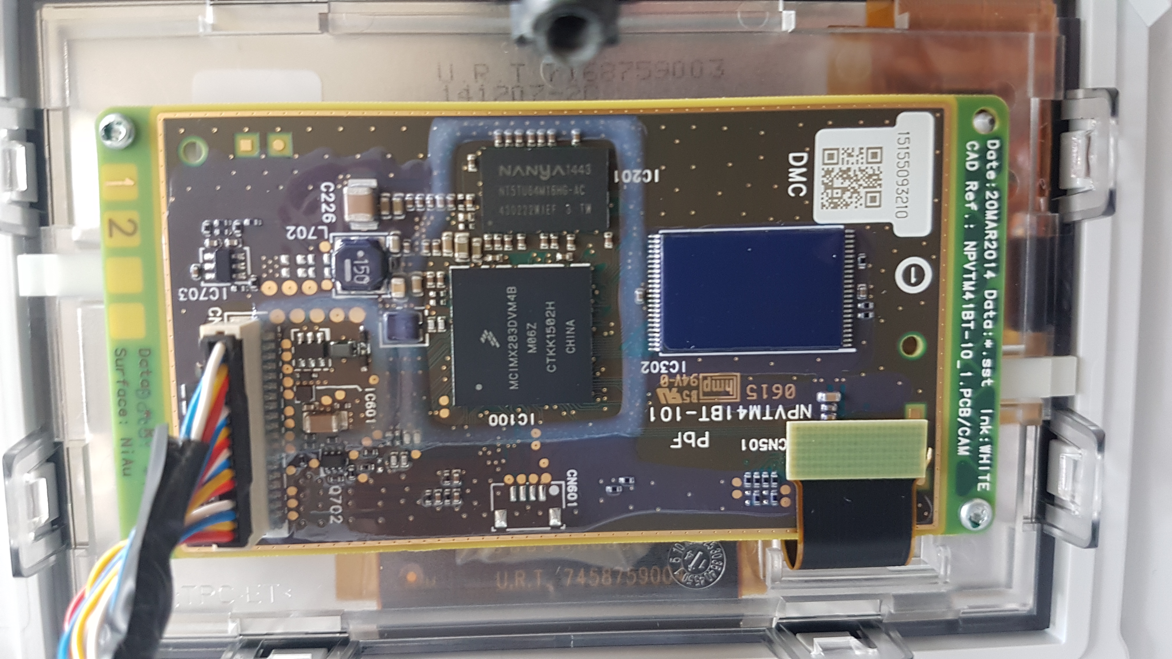
This picture shows the back of the display panel. As you can see, the design dates back 7 years but the product is a nickel and gold plated circuit board - a sign of top quality invested into it.
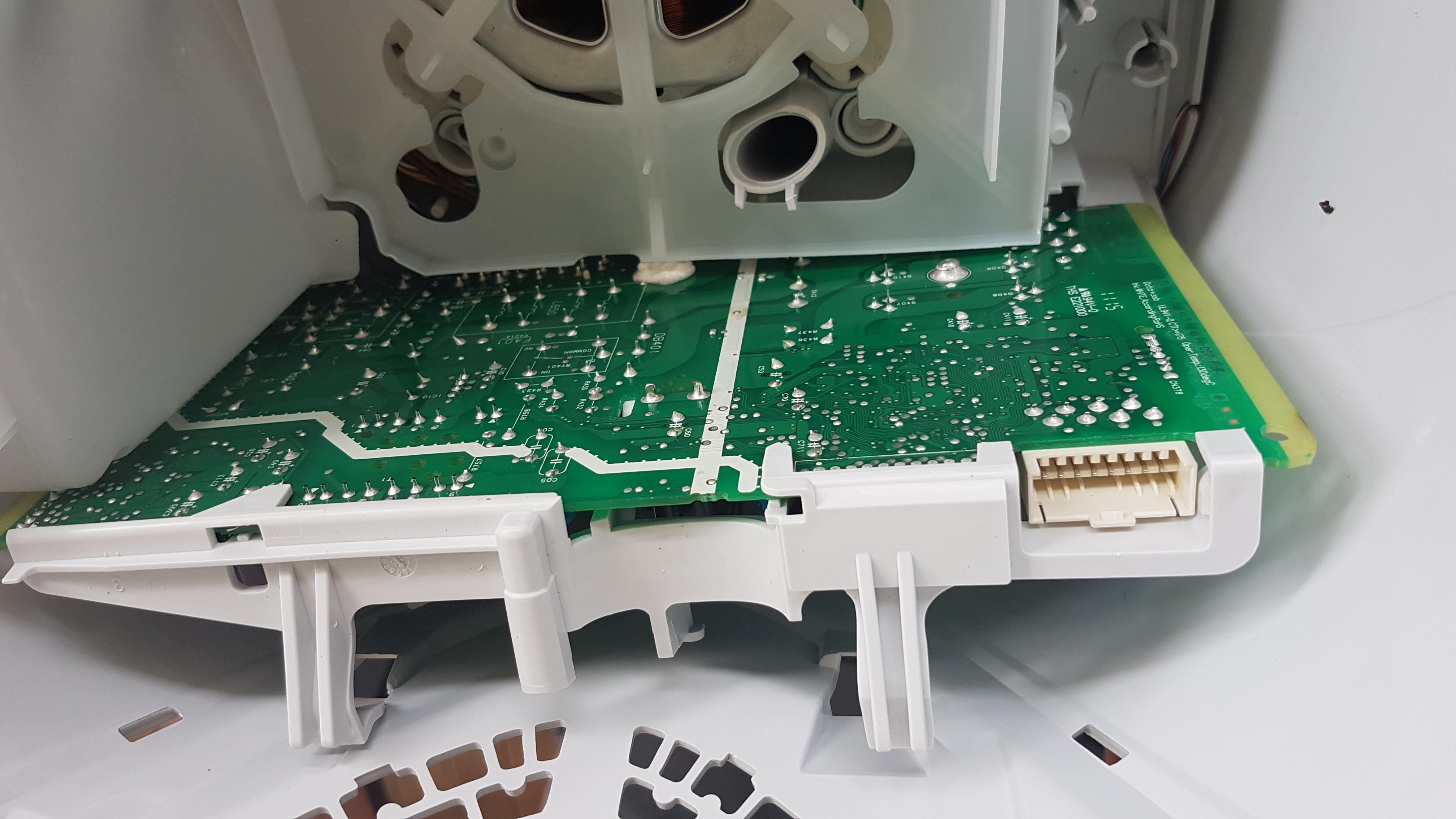
This picture is of the back of the circuit board that appears to contain, probably amongst other things, the motor controller circuit.
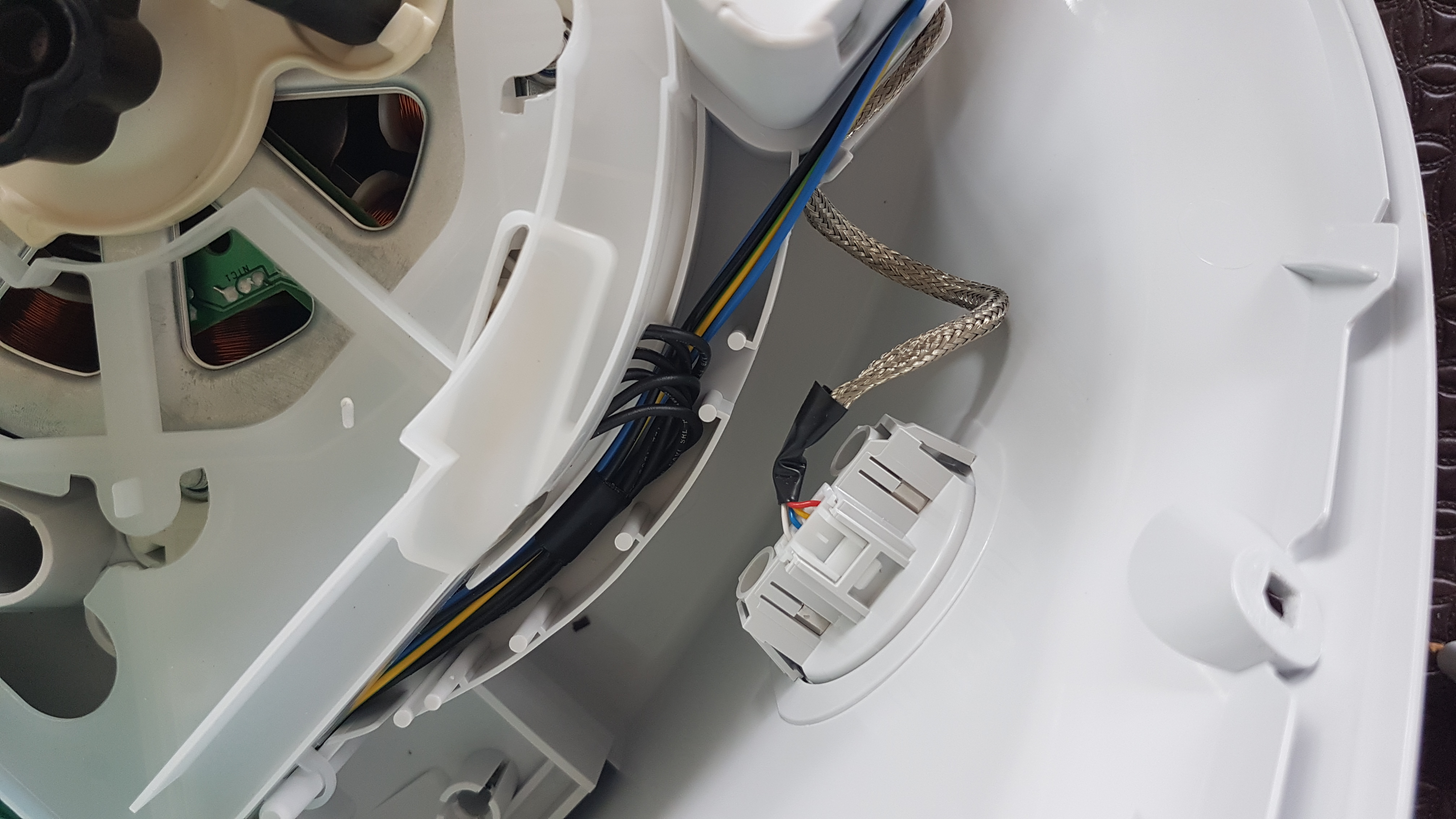
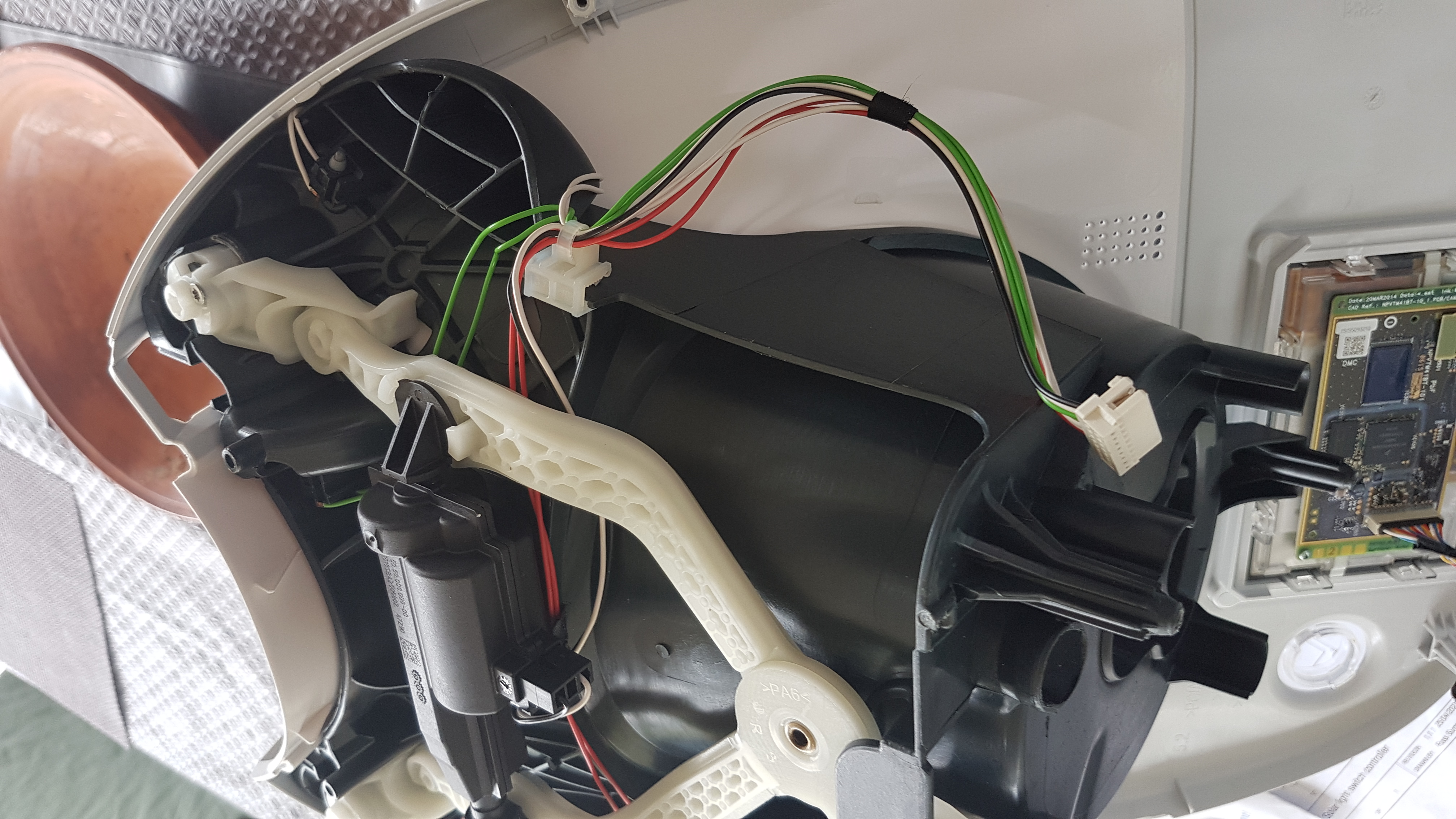
You can see here the container that is used to house the power cable when it is pushed in. This container ensures that the power cable does not interfere with any of the other componentry, including the weight measuring system.
This is the inside of the USB recipe chip and cook key holder.
This view of the base of the mixing bowl housing also shows the controller/display screen also attached to the same side. The screws that hold the unit together are all the same fitting, meaning you only need one screwdriver (albeit with a star tip) to open up and service the entire unit. The TM5 is a marvellous piece of German engineering!
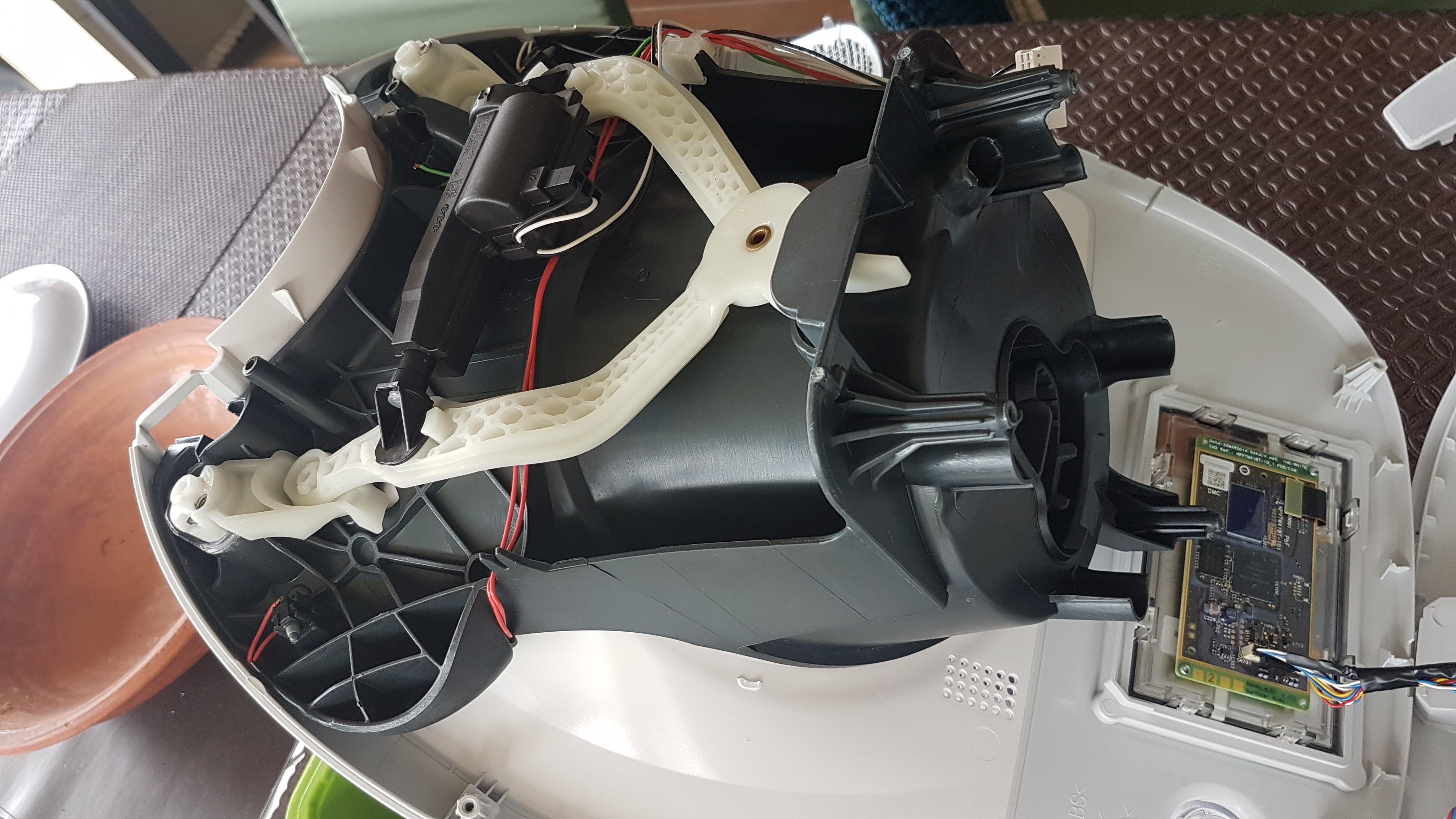
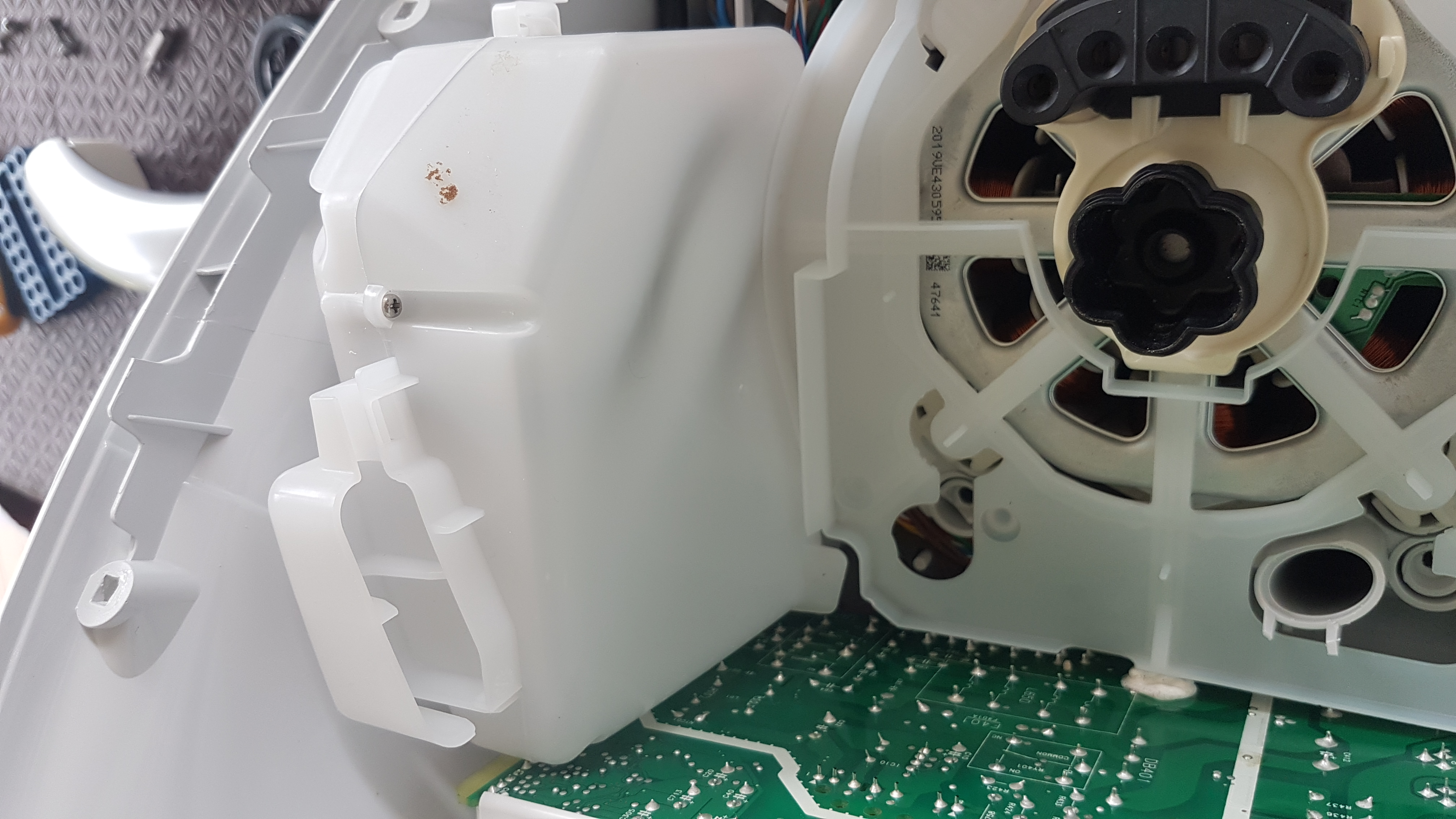
This is another view of the bowl housing looking from underneath.
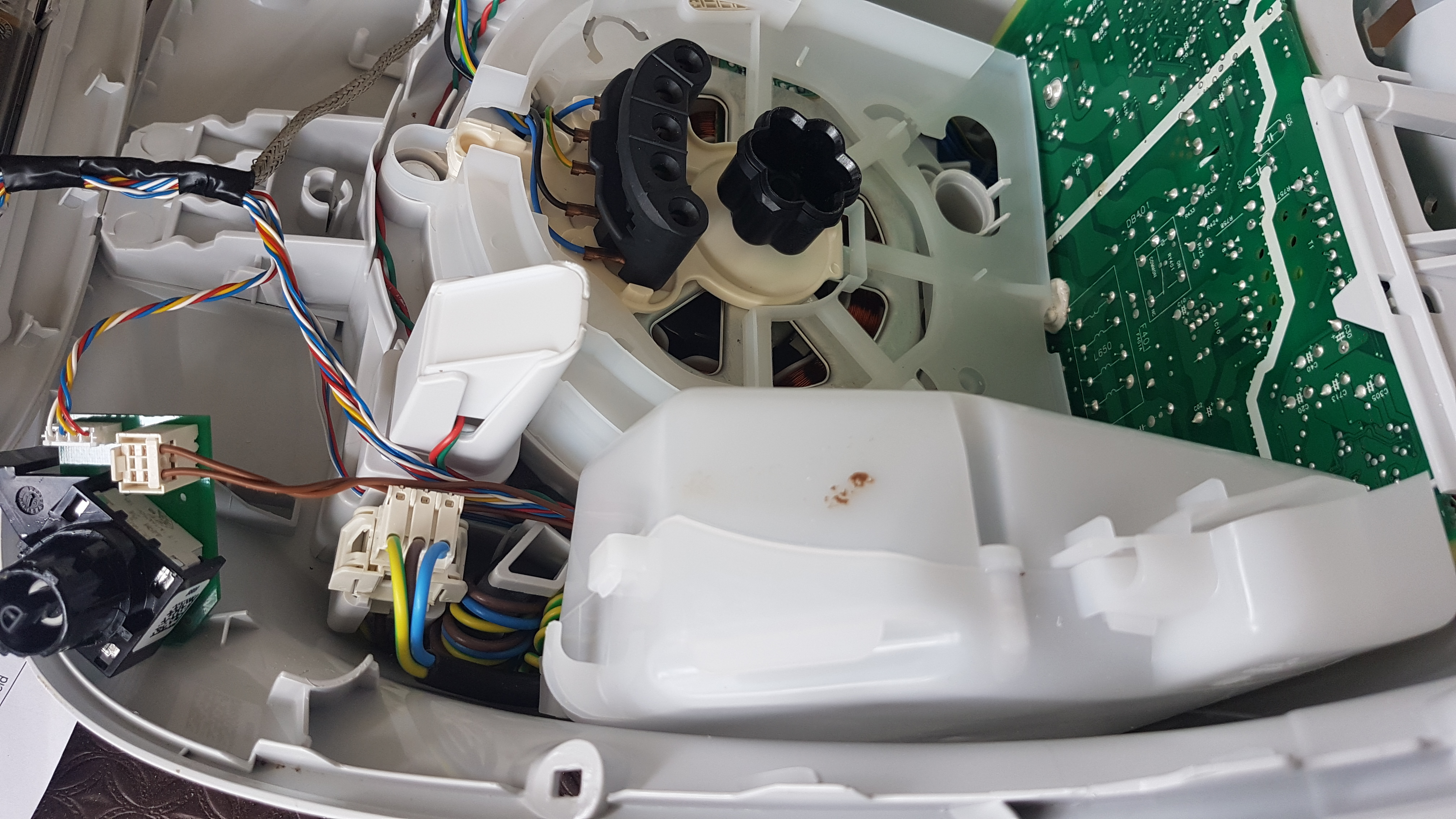
A view of the motor. Also in the bottom of the image you can see the Selector. Mine is a little defective when setting the time (it jumps around a bit, either forward or backward, irrespective of the direction the selector is turned, but not always and not usually by much) but not when setting the speed, suggesting a software fault.
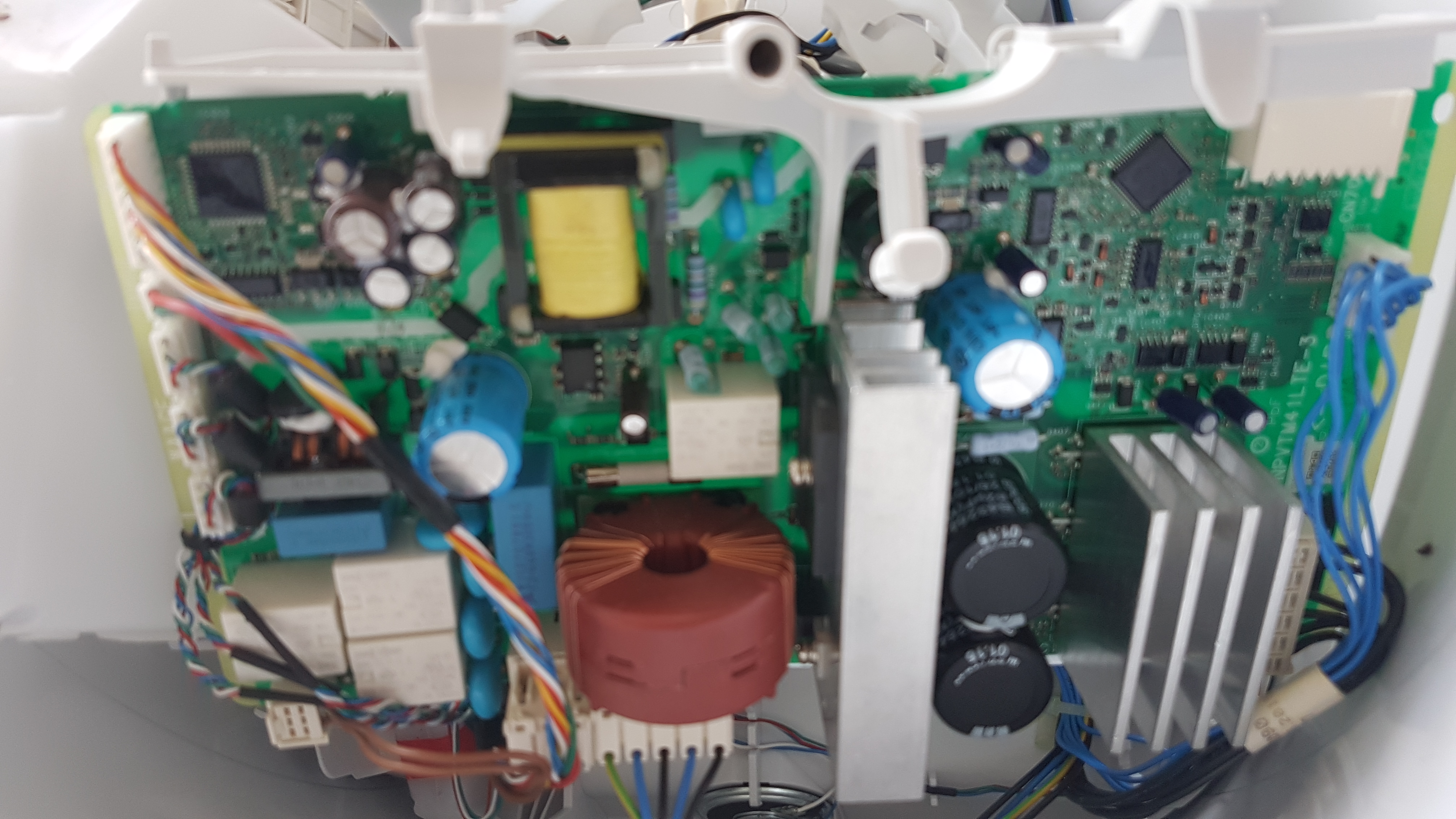
The motor control circuit board can be seen here. The circuitry in the top right of the picture suggests that it maybe does a little bit more than that.
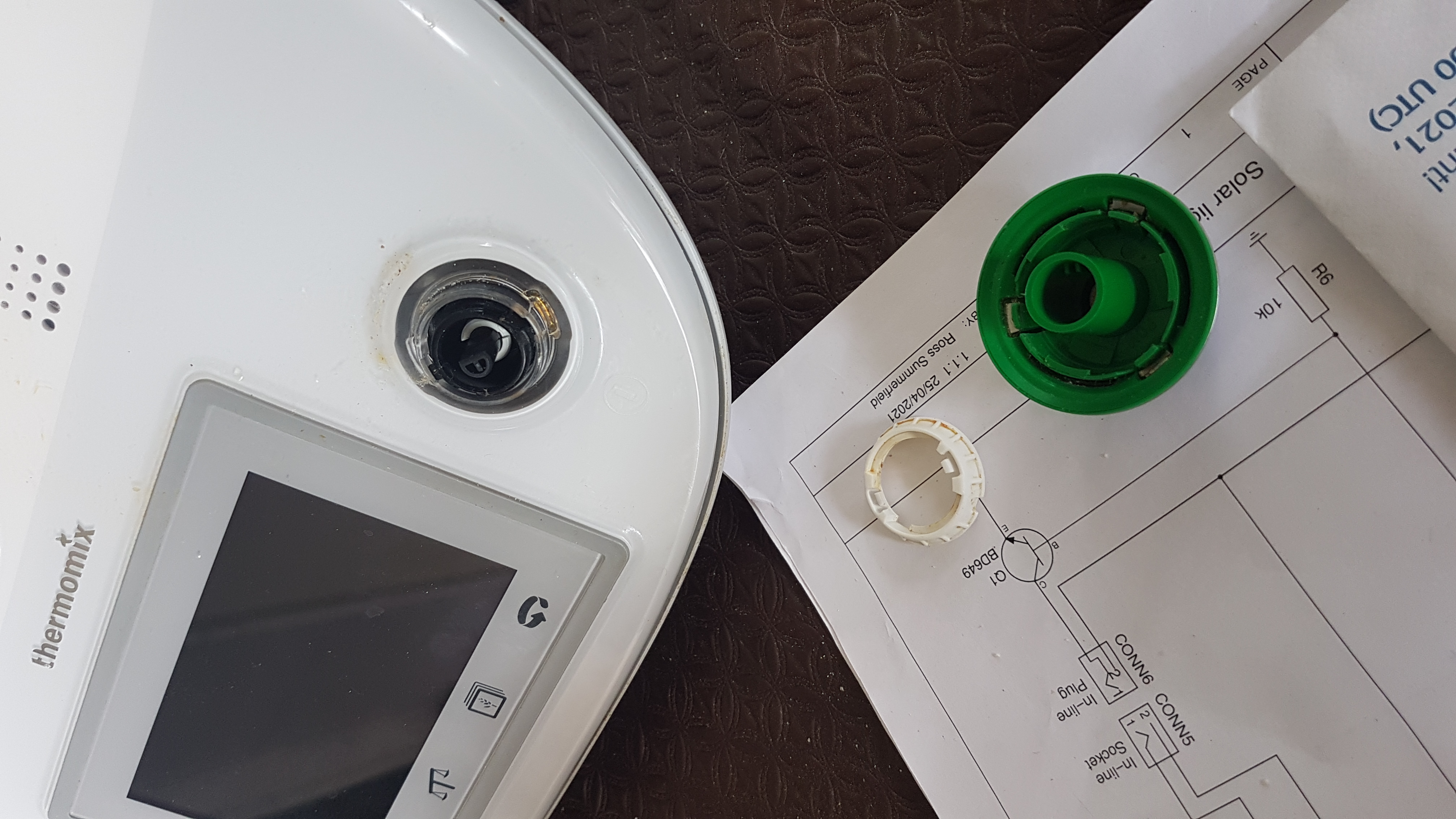
This shows the selector assembly. The white thing is a locking ring. To properly open the device, in addition to removing the screws at the back an underneath, and in addition to removing the handle (after the two screws at the top are removed), the selector needs to be disconnected. The leads on it are quite short and it does have a bit of plastic that holds it to the bottom of the unit.
