![]()
The Control Structure Diagram (CSD) is an algorithmic level diagram intended to improve the comprehensibility of source code by clearly depicting control constructs, control paths, and the overall strucutre of each program unit. The CSD is an alternative to flow charts and other graphical representations of algorithms. The major goal behind its creation was that it be an intuitive and compact graphical notation that was easy to use manually and relatively straightforward to automate. The CSD is a natural extension to architectural diagrams, such as data flow diagrams, structure charts, module diagrams, and object diagrams.
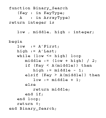
In the figure located below, you will see the source code for an Ada function entitled Binary_Search. It implements a binary search algorithm by using an if..elsif statement nested within a while loop. Even though this is a very simple function that is indented well, the various levels of control within the function are not immediately obvious.
  |
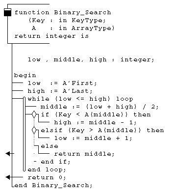
The adjacent figure contains the CSD for Binary_Search. In this figure, the various levels of control within the program are immediately obvious. At the topmost level there are four statements: two assignment statements, a while loop, and a return statement. The while loop defines a second level of control flow consisting of an assignment statement and an if..elsif construct. Finally, each of the three branches of the if..elsif statement are associated with a single statement.
![]()